REGAL
Checkout securely with:

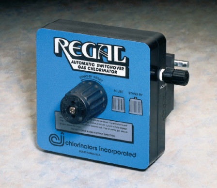
The principal use of the REGAL Gas Chlorinator is to chlorinate water, wastewater and industrial process water with gas chlorine. The simple, efficient design has made REGAL Gas Chlorinators the industry standard. Built with heavy duty corrosion resistant parts, REGAL Chlorinators provide safe, long-lasting service.
The REGAL Chlorinator is a vacuum-operated, solution feed type, designed for mounting directly on a chlorine cylinder valve or for mounting on wall manifold or ton container adaptor, REGAL Model TAY-200. The chlorine flow rate is manually adjusted and is regulated by a spring opposed diaphragm regulator which also contains the safety shutoff valve. Vacuum is provided by a highly efficient water operated ejector which is close coupled with the chlorine solution diffuser. The ejector assembly contains a back flow check valve.
FEATURES
The REGAL Chlorinator incorporates the very best available materials with the latest technology in design and construction, to reduce maintenance, simplify construction and improve operation.
CAPACITIES
Dual scale metering tubes are provided with the following maximum capacities. Minimum feed rate is 1/20th of maximum.
Model 210 - 4, 10, 25, 50 or 100 PPD (75, 200, 500, 900 or 2000 gms/hr)
Model 220 - 250 PPD (5 kg/hr)
Model 250 - 500 PPD (10 kg/hr)
FLOW RATE ADJUSTMENT
Manually adjustable by means of a flow rate control valve located at the top of the flow meter. Flow rate is then regulated by a special spring opposed diaphragm operated valve. The system is automatic. It will go off and on as the ejector water is turned off and on and will return to the pre-set flow rate.
EJECTOR REQUIREMENTS
The standard ejector is designed to withstand static back pressure up to 200 psig (14.1 kg/cm2). The amount of water required to operate the ejector depends upon the chlorine feed rate, water back pressure and water supply pressure available. Generally, the higher the chlorine flow and higher back pressure, the greater the water flow is required.
OPERATION
The chlorinator is clamped on the chlorine cylinder valve. The ejector assembly is normally attached to the solution diffuser at the point of injection). A vacuum line connects the ejector to the chlorinator. Water, under pressure is forced through the ejector nozzle which creates a strong vacuum in the ejector body. This pulls gas into the ejector through a special back-flow check valve and then into the nozzle outlet. The gas mixes with the ejector water and is discharged through the diffuser into the water being treated. The ejector vacuum is transmitted back to the chlorinator through the vacuum line; then through the rate valve and the flow meter and to the back of the diaphragm. With sufficient vacuum, the diaphragm moves backward, opening the spring loaded inlet regulating valve to allow chlorine to enter from the cylinder. The chlorine passes through the flow rate indicating meter, flow rate adjusting valve and to the ejector.


SPECIFICATIONS
The Chlorinator(s) shall be of the REGAL Model 200 Series manufactured by Chlorinators Incorporated located in Stuart, Florida with capacities ranging from 4 to 500 lbs/24 hours (PPD). It will be a vacuum operated solution feed type and mount directly on the chlorine cylinder valve by means of a positive yoke type clamp having an integral tightening screw with slide-bar handle. All regulating, metering, flow adjusting and safety functions shall be incorporated in the cylinder mounted unit. The inlet safety shut-off/vacuum regulating valve shall be of capsulated construction, easily removable as a unit from the outlet side of the yoke for ease of inspection, cleaning or maintenance. Vacuum shall be created by an ejector assembly connected directly to the chlorine solution diffuser. The assembly shall consist of a single piece venturi-recovery throat to prevent mis-alignment; also, a back flow check valve to prevent water from entering the gas system. The check valve shall be of positive, tight shut-off, unitized design not requiring springs or diaphragms for tight closing.


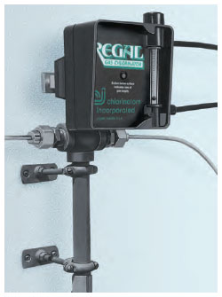
Ton Cylinder Installation Example Wall Mount Installation Example

CONTENTS GUIDE MODEL 210
1 each Model A-820 Vacuum Regulator with 3/8" Vent and Vacuum Fittings
1 each Model A-920 Ejector Assembly including Nozzle, Back Pressure Check Valve, Spray Diffuser and Vacuum Fitting
(OPTIONAL: A-921 Low Pressure Ejector, A-927 Hi/Lo Pressure Ejector, A-950 Dual Check Valve Ejector)
25' VT-1, 3/8" Vent and Vacuum Tubing
10 each G-201 Lead Cylinder Gaskets
1 each Z-296 Rate Valve Tool
1 each Z-297 Vent Line Bug Screen
Approximate Shipping Weight: 8 lbs
CONTENTS GUIDE MODEL 220
1 each Model A-822 Vacuum Regulator with 1/2" Vent and Vacuum Fittings
1 each Model A-922 Ejector Assembly including Nozzle, Back Pressure Check Valve, Spray Diffuser and 1/2" Vacuum Fitting
(OPTIONAL: A-923 Low Pressure Ejector, A-950 Dual Check Valve Ejector)
25' VT-2, 1/2" Vent and Vacuum Tubing
10 each G-201 Lead Cylinder Gaskets
1 each Z-296 Rate Valve Tool
1 each Z-297 Vent Line Bug Screen
Approximate Shipping Weight: 9 lbs
CONTENTS GUIDE MODEL 250
1 each Model A-825 Vacuum Regulator with 5/8" Vent and Vacuum Fittings
1 each Model A-925 Ejector Assembly including Nozzle, Back Pressure Check Valve, Open Diffuser and 5/8" Vacuum Fitting
(OPTIONAL: A-926 Low Pressure Ejector, A-950 Dual Check Valve Ejector)
25' VT-3, 5/8" Vent and Vacuum Tubing
10 each G-201 Lead Cylinder Gaskets
1 each Z-296 Rate Valve Tool
1 each Z-297 Vent Line Bug Screen
Approximate Shipping Weight: 10 lbs
NOTE: Wall-Mounting Manifold Assembly and Direct Ton Container Mounting Adaptor (TAY-200) are available as optional accessories.